Friday, June 13, 2014

The Fleet Expands

Recently I have been pretty busy working on various things, as illustrated below, including remaking a chassis to fit under 1709, adding finishing details to a pair of Z12 class locos and assembling some laser cut FG carriages I drew in CAD and doing up a Badgerbits TAM sleeping car: 


Wednesday, April 23, 2014

Virtually Finished Non Air Hoppers

A string of N scale Non Air Hoppers


The finished string of the start of hopefully many hoppers stand ready for use behind NSWGR 1803 with matching S truck. The S truck has a bit of brass wire bent in such a way to hold onto the chain link coupling at the end of the 'string' of hoppers. 


Microscale letters were used to represent the different colliery letters.


Chain was used to couple the hoppers together permanently and enough slack is left so that a slight gap is allowed between the buffers. 


Closeup showing the brass chain used at the end of the string of hoppers.


Friday, March 14, 2014

Building Non Air Coal Hoppers in N Scale


Non Air NSW Coal Hoppers in N scale 


Several Peco NR119 chassis kits were purchased and some Evergreen 2060 styrene for the sides to follow on from an article in the June 2011 Australian Model Railway Magazine. The photos should be pretty self explanatory. 


Attaching the framework on the outside of the hopper. 


The virtually structurally complete hoppers.


Friday, February 21, 2014

NSWGR Z19 and Z12's - Finishing off one thing and starting another.

Z19 paint job and a pair of Z12's

It's been a while since an update but below the series of photos should tell the tale:


The Z19 - 1957 painted plain black and lettered and the finished product below:

After dreaming about it for years I finally have got around to it - scratch building a pair of Z12 class locomotives in N scale. To simplify the construction of the duo I decided to make duplicates of all parts and put them together at the same time. 


The frames soldered and screwed together to permit accurate drilling of the axle holes and the material for the rods. 


1 frame side cut out prior to joining showing the detail cut out with a jeweller's saw.


Below is one of the frames being screwed together with turned spacers. The 12 BA screws were used to hold the frames as they were set up before being finally permanently soldered together. Note that the bearings have not yet been inserted into the axle (bearing) holes in the frames. 


The two locomotive chassis following assembly - the front wheels are from Gopher Models and the driving wheels are Fleischmann wheels with turned down flanges. 


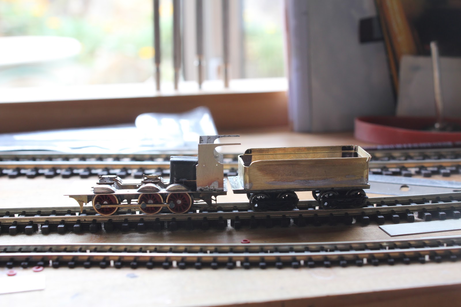
The locomotive takes shape as a tender is added to complement the engine frame. 
Body work added following lots of fiddling around with bits of brass and nickel silver. Note the loco tilting forward due to the engine being nose heavy. The motor is mounted within the smokebox.


Sunday, April 7, 2013

Slow progress...on the Z19 with Baldwin Tender

Months go by and I do a bit here, and there on the loco that has sat on my workbench for quite some time now. The following photos show progress made on the body and the construction of the tender. 


The body is almost ready for final detailing, a drawbar needs to be fashioned to join the tender and engine. Pickups need to be fitted to the engine, but in a cool stroke of God's grace the engine has taken its first steps under its own power with pickups fitted to the tender. The piano wire link between tender and engine works! 


Wednesday, November 28, 2012

Z19 and Baldwin Tender


The progress on my Z19 continues... shown here is the progressive assembly and construction of the chassis. 


Quatering was carried out by eye and was fairly easy to achieve. I have found that the use of a 'stiff' gearbox to hold a wheel in place, the one that all the rest are quartered in relation to really helps. 


Finding appropriate sideframes for the tender bogies was a bit tricky...however a Bachmann 4-4-0 old timer tender chassis proved to have an answer... 
The horrible small 'wheels' ( I say wheels because they skid) were removed and new axle points drilled with Gopher Models wheels fitted. Wheels can be bought from http://www.badgerbits.com.au/


After the wheels and base of the tender had been sorted out, from brass and PCB the sides were looked at....

Brass formed the solution and care was necessary in marking out the various 'landmark' sections, as the sides were to be formed and bent from one piece to simplify the assembly process. 


The bent top edges were done using scribing and the jaws of my unimat vice. 


The finished bent tender top prior to soldering to the chassis. 


The footplate has had the 'splashers' added. 


Attention turned to the cutaway cab, sweating two sheets of brass together and the plan side glued to permit identical cutting. 


The finished cab soldered to the footplate and accompanying tender.